Process: Simple Buffer
This is the video version of the buffering concept utilizing Esri software, the website text in general will be more up to date, since the creation of video is a very long time consuming process.
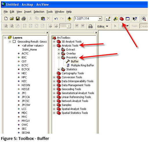
A simple buffer creates a single surface, if one buffering surface crosses another they will be overlapped. The buffering tool is in the Analysis Toolbox and the tray (sub-section) of proximity, in this tray there are two different tools which will be used in this technical skill lesson, for simple buffering select the buffer tool. Before beginning the buffer process place a state map with county boundaries onto ArcGIS Desktop and a point shapefile fully contained
within the state. Data is provided for this lesson, but the learner may select their own data as long as these criteria are met. The point shapefile must have an appropriate projection. In figure 5 the Toolbox has been opened and the arrows point to the buffering tool.
within the state. Data is provided for this lesson, but the learner may select their own data as long as these criteria are met. The point shapefile must have an appropriate projection. In figure 5 the Toolbox has been opened and the arrows point to the buffering tool.
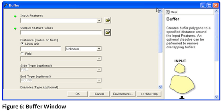
The next box request the location that the output file will be saved, the buffer operation will create a new polygon shapefile, so a location and appropriate naming convention should be used and not just the default name. An example name might be KY_KCTCS_buffer_25. The name shows the state, the information with the 25 for 25 mile buffer
about the point data. The distance is a linear distance and 25 miles was selected for this example. All other items will remain at the default values.
about the point data. The distance is a linear distance and 25 miles was selected for this example. All other items will remain at the default values.
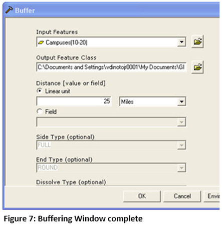
The completed form appears like Figure 7: Buffering Window complete. It is important to note that the distance feature has two specifications one the distance and the other the units of the distance. If the layer does not have an appropriate projection than it will not give the proper units to use. Click on ok to execute the creation of buffers. The buffering process will begin and a dialogue window will be at the bottom right corner of the screen. The KCTCS Campus file is updated periodically so the results may look slightly different.
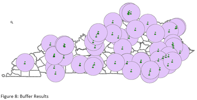
The map figure 8 shows buffering on top of buffers, buffers crossing outside of the state and areas not covered by a 25 mile buffer. The circles that are created are a new polygon shapefile Figure 8: Buffer Results and can be modified like any other shapefiles, such as boundary colors, fill etc. or used as a clipping boundary. The learner should also create buffers of lines and polygons. For inside buffering of a polygon the distance is negative and for outside the distance is positive.